Oil Water Separator Design Manual
Separator designs may vary are liquid containment structures that provide sufficient hydraulic retention time to allow oil droplets to rise to the surface.
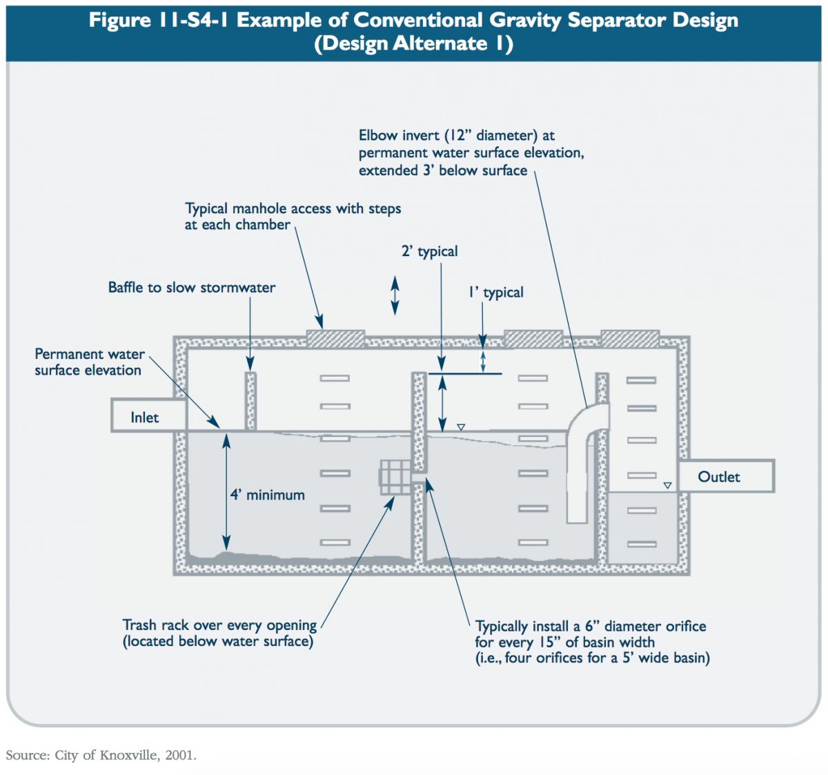
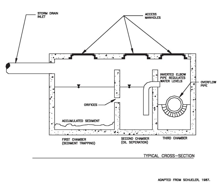
Oil water separator design manual. Three variations are presented in this manual. Design of conventional and parallel plate oil water separator systems requires proper characterization of the wastewater establishment of the design flow and required effluent quality sizing of. The separated water is purified for direct sewer or ocean discharge. A forebay inlet chamber an oil separator cell and an afterbay outlet chamber.
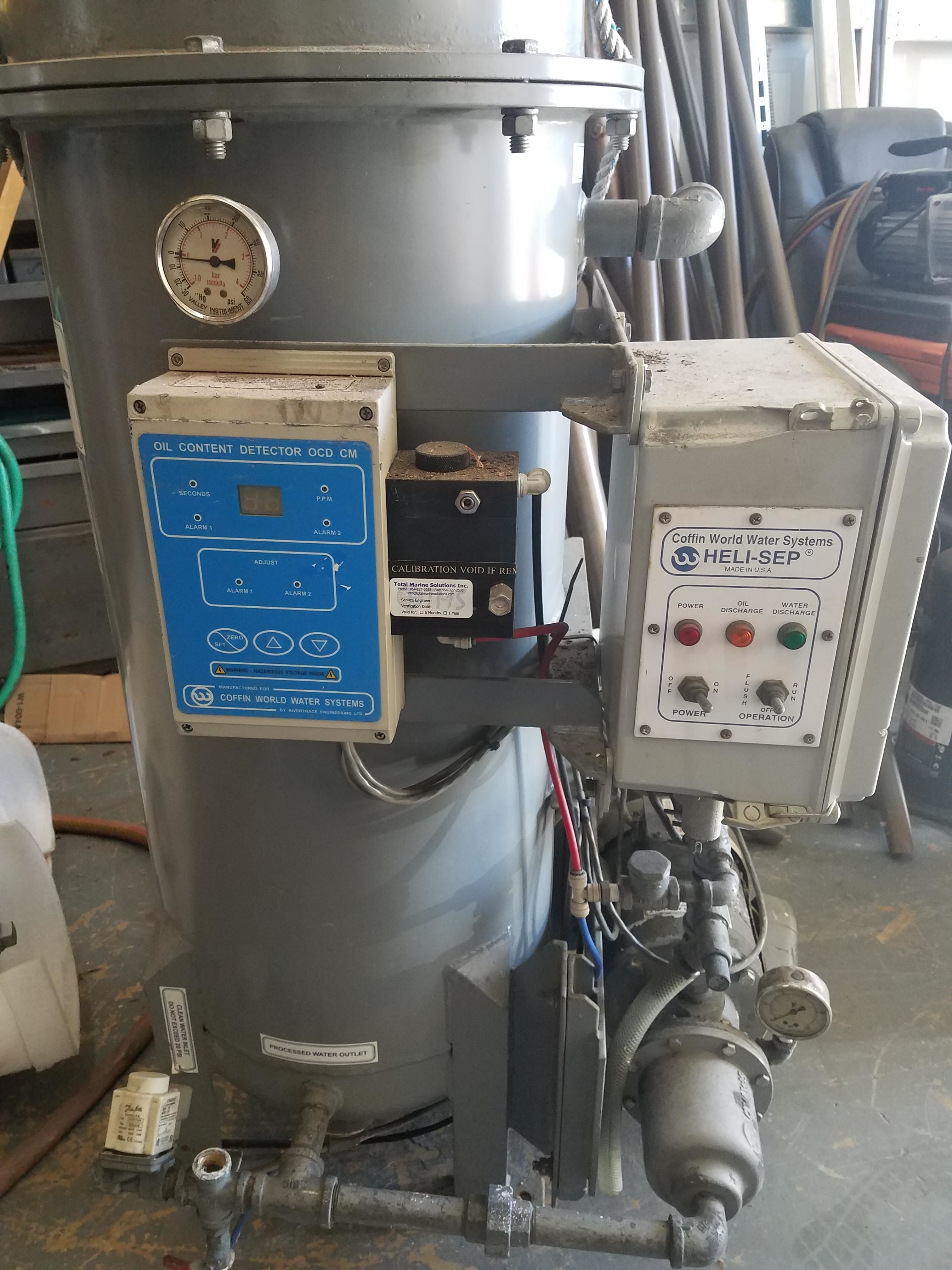
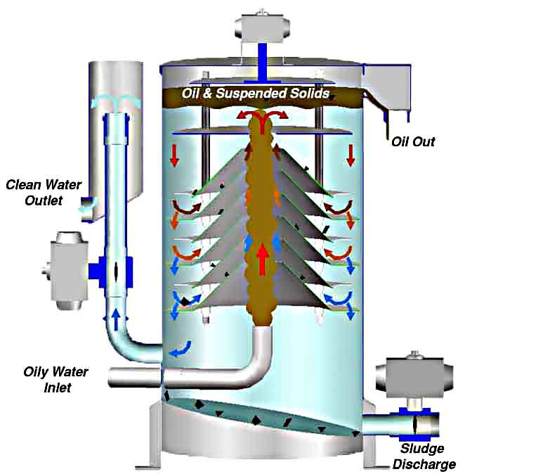
The forebay is primarily to trap and collect sediments encourage plug flow and reduce turbulence. It consists of three major parts the oil separator unit filter unit and the oil content monitor and control unit. This separation of the liquids from the gas phase is accomplished by passing the well stream through an oil gas or oil gas water separator. Liquid liquid coalescer design manual acs oil water separatorsutilize patented technology to separate oily waste water.
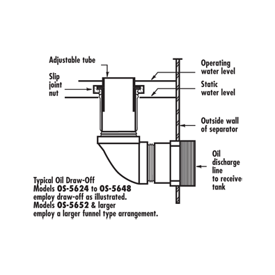
Applications include oil spill clean up for marine power plants refineries vehicle terminals and countless others. The petroleum and water treatment industries as well as the hvac systems employ the various separators in their daily operations. The design utilizes the difference in specific gravity between oil and water buoyancy force. The oil forms a separate layer that can then be removed by skimmers pumps or other methods.
Spill control sc separators are the least expensive and complex of the three. Description oil water separators are multi chambered devices designed to remove hydrocarbons from stormwater runoff as it moves through the device. Different design criteria must be used in sizing and selecting a separator for a hydrocarbon stream based on the composition of the fluid mixture. 33 2 1 design oil separators shall be divided into three compartments by baffles or berms.
Oil Particle Separators Ct Stormwater Quality Manual
Http Www Deq Idaho Gov Media 618110 18 Pdf
Oil Grit Separators
Http Www Geotechenv Com Manuals Geotech Oil Water Separator Manual Pdf
Https Www Oilandwaterseparator Com Wp Content Uploads 2014 12 Stormwater Processing Separator Design 2014 Pdf

Separation Equipment Company Inc Products Marine Heli Sep Oily Water Separators

Api Oil Water Separator Wikipedia
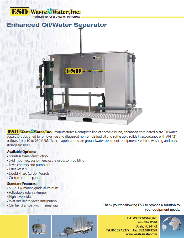
Oil Water Separators Esd Waste2water

Oil Water Separator

Oil Water Separator Filter The Ultimate Guide Filson Filter
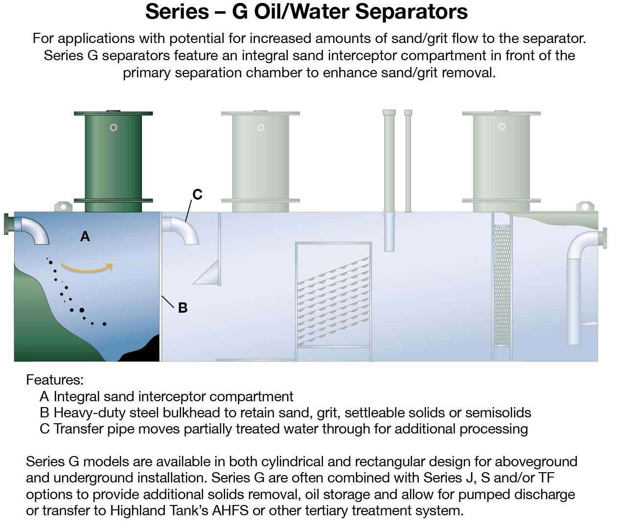
Oil Water Separators Highland Tank

Api Type Oil Water Separators
Https Www Nistm Org Pdf Aymong Pdf
Below Grade 0 5000 Gpm Oil Water Separator Technologies
Above Grade Oil Water Separator Technologies

Oily Water Separator Ows Youtube
Oil Water Separator Tank Sensing Solution Veeder Root

Oil Water Separator Principle Youtube

Oil Water Separator Systems Slant Rib Coalescing Src Fiberglass Tank Srm Parkson Corporation

Diesel Filter Oil Water Separator For Fs19732 3973233 Replacement Parts Separators Oil Water
Oil Separators Built By Rockford Separators Rockford Illinois

Design And Sizing Of An Oil Water Separator

Pin On Heat Treatment Water Equipment
Oil Water Separators Tramp Oil Removal System Fatboy Ows Filter Technology Engineered Systems
Https Encrypted Tbn0 Gstatic Com Images Q Tbn 3aand9gcthvrzkrf 1g0w0it8grau0azuam E1nlebxwrpockyz6fhbbsi Usqp Cau
Https Your Kingcounty Gov Dnrp Library Water And Land Stormwater Stormwater Pollution Prevention Manual Oil Water 20separator Information 20sheet Pdf

Victor Marine Ltd Oily Water Separator Process Youtube

Oil Water Separators Prab

Maxisep Oil Water Separator

Global Tek Oil Water Floating Skims Oil Water Floating In Water Environmental Engineering
Https Www Stormwaterpartners Com Sites Default Files 17 12 13 Oil 20water 20separator 20api 20type 20ccsm2015 Book 4 20errata 11 Pdf
Https Knoxcounty Org Stormwater Manual Volume 202 Chap4 Section 4 4 4 4 7 Gravity Oil Grit Separator Pdf

Oily Water Seperator Bilge Water Seperator Oil And Water Seperator Youtube

Above Ground Oil Water Separator Can Am Instruments Ltd

Oily Water Separator Marine Wikiwand

Centrifugal Water Oil Separator Wikipedia

Yuchai 4d24 4d24t Series Off Highway Diesel Engines Are Developed By Raywin Powertrain Techno Operation And Maintenance Preventive Maintenance Fuel Efficient

Econosep Oil Water Separator

Oil Water Separator Ows 100 Capacity 1 5 M3 Per Hours Id 11664077497

Mercer International

Posi Zorb Air System Products

Oil Water Separator Systems Fox Environmental Systems
Https Www Stormwaterpartners Com Sites Default Files 17 12 13 Oil 20water 20separator 20coalescing 20plate 20ccsm2015 Book 4 20errata 12 Pdf

Helping The Environment H2m Provided Water Wastewater Environmental And General Professional Engineering Services To Calpin Storage Tanks Oil Water Bethpage

Photos Of The Oil Water Separator Valves Packaged For Shipment To Our Client After Assembly Testing And Palletizing These Items Oil Water Midland Separators

Use For Volvo Fuel Water Separator 20514654 Fuel Water Separator Car Filter Volvo
Oil Water Separators Oldcastle Infrastructure
Https Www Tad Usace Army Mil Portals 53 Docs Taa Aeddesignrequirements Aed 20design 20requirements 20 20oil Water 20separators Jan 10 Pdf